Pose & reference
Where is my fingertip relative to the key? Which body, object, or world frame gives the instruction meaning?
BODY SYNTONY / A RESEARCH THESIS BY TODD MUSCAT
FIELD STUDY 003 · 2026What if intention had a physical representation? Pose, forces, surfaces, tangents, and normals—expressed through the body’s relationship with its world. From APT’s geometric insight to a proposed interface for learning, prediction, and motion.
Follow the story 01 — 0401 THE GEOMETRY OF INTENTION
MIT · 1956–1959Imagine yourself as the cutting tool. Follow the geometry. Let the computer work out the motion.
$$ Contouring: surfaces already defined
$$ GS: supporting ground surface
$$ DS: curved lateral drive surface
$$ CS: terminating check surface
$$ Cutter engaged; forward direction set
CUTTER / 10
PSIS / GS
TLAXIS / 0, 0, 1
TLRGT
GOFWD / DS, TO, CSGOFWDGo forwardTANTOTangent toTO / ON / PASTRelationships to a boundaryGS · SupportThe cutter end remains on the ground surface.
DS · GuideThe cutter flank follows the wall; the center path is offset by its radius.
CS · StopTO ends the move at first cutter contact with the check plane.
Original geometric illustration inspired by the supplied references. Scrub or play the path. This is a prescribed contour demonstration, not an APT interpreter or cutting simulation.
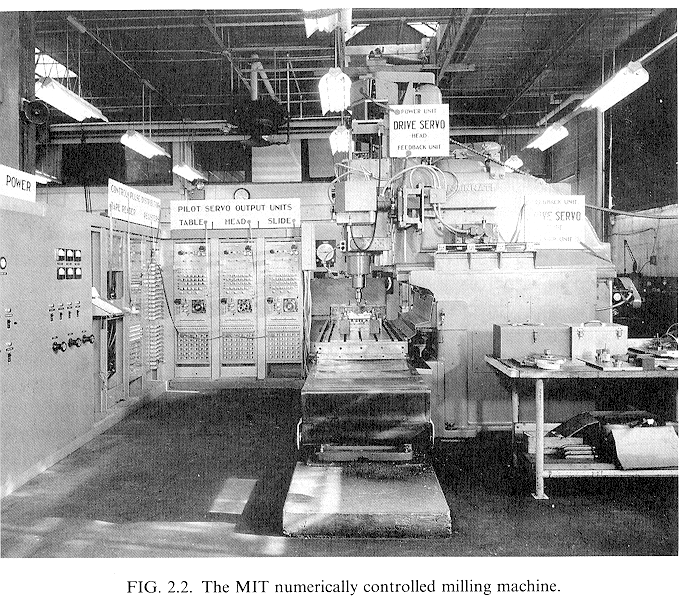
Douglas T. Ross led APT’s development at MIT with Air Force support and aircraft-industry collaboration. Automatically Programmed Tools turned descriptions of geometry and tool motion into paths for numerically controlled machines. NC hardware came first; APT made complex machining far more practical to program. [1]
APT can describe motion in relation to ground, drive, and check surfaces. Its processor calculates cutter locations; a postprocessor translates them for a particular machine. The APT fragment describes three simultaneous relationships: the cutter end follows the ground surface, its side follows the drive surface, and the check surface terminates the move. The illustrated ground surface is planar; the curved drive surface determines the contour. The tool axis remains normal to the ground surface. That relational contouring language is the foundation for the BodySyntonic proposal. [2]
MIT demonstrates numerical control.
Ross’s team develops APT with industry.
First APT language standard: ANSI X3.37.
RAPT brings geometric relationships to robot assembly.
A foundational language for NC and CAM. The first APT ANSI language standard was published in June 1974. [3]
02 BODYSYNTONIC / A PROPOSED REPRESENTATION
INTENTION MADE PHYSICALFollow a surface. Orient toward its normal. Apply force. Reach a boundary. Adapt as contact changes.
BodySyntonic asks whether these relationships can become a shared representation for learning, reasoning, and motion. BRL—Bodysyntonic Robot Language—is its proposed human-readable expression.
Where is my fingertip relative to the key? Which body, object, or world frame gives the instruction meaning?
Approach along the surface normal. Control lateral drift in the tangent plane. Follow geometry as it moves.
Describe desired interaction: contact mode, force bounds, compliance, friction, and slip.
Specify onset, strike velocity, duration, and release. Define the physical evidence that the action succeeded.
An intention describes what should hold while the body moves. Different joint trajectories may satisfy the same relation. A guide surface can be virtual; a contact surface participates in physical interaction. Their roles remain explicit.
Keep measured contact, pose, and velocity distinct from intended conditions. Bind every relation to tracked entities, coordinate frames, units, tolerances, and uncertainty. The representation can be a typed graph or tensors, with BRL as a readable view.
03 FROM DESCRIPTION TO PREDICTION
LECUN · WORLD MODELS · INTENTIONA proposed progression of ideas: language, action, predictive world models, and explicit body–world relationships.
01 / DESCRIBE
Express a task and reason through a symbolic description.
“Play this note.”02 / ACT
Condition robot actions on visual observations and language.
observation → action03 / PREDICT
Learn representations; action-conditioned variants predict consequences.
state + action → future04 / STRUCTURE INTENT
Represent the bodily and physical relationships a task requires.
relations → objectivesLLM → VLA → JEPA → BodySyntonic is our conceptual progression, not a historical succession or replacement claim. VLA policies and JEPA world models can work together; BodySyntonic is a proposed interface across them.
LeCun’s autonomous-agent proposal separates prediction of the world from evaluation of outcomes and selection of actions. We use “intention” here for explicit desired relationships and completion criteria—a candidate input to that evaluation and planning process. [7]
V-JEPA 2-AC provides a concrete reference: it predicts future representations conditioned on actions and proprioception, and supports planning toward image goals. [8]
Score predicted trajectories against contact, pose, timing, and force objectives. Train additional readouts for control-relevant relations. Condition an action proposer on the same intention representation.
A “meta-transformer” could learn to translate observations and a task into this structured intention, or condition candidate actions on it. The first prototype can use an explicit parser and planner; the transformer is a later, testable architecture choice.
Sense the body, key, contact, and uncertainty.
Bind intention to entities and physical quantities.
Roll out actions and score the relationships.
Execute a short segment and update the state.
A visual embedding does not automatically provide contact force or a calibrated surface normal. Those quantities need geometric estimation, sensors, simulation labels, or trained readouts. The learned model and the physical measurements must be connected explicitly.
04 FIRST EXPERIMENT / ONE PIANO KEY
SMALL TASK · RICH PHYSICSLocate it. Approach. Establish contact. Strike with controlled timing and velocity. Release. Observe the note.
Approach the contact patch along the key’s normal.
Geometric illustration. The stroke is scripted; sound is not simulated.
intention strike_key {
  body: fingertip
  reference: key.contact_frame
  guide: key.press_path
  contact: key.top_patch

  approach along -key.normal
  align finger.axis, -key.normal
  limit tangential_slip

  strike {
    onset: requested_time
    velocity: calibrated_strike_velocity
    outcome: requested_midi_velocity
  }

  release after requested_duration
  observe note_on, note_off,
          key.travel, midi.velocity
}Our proposed bench rig uses a single actuator, a compliant fingertip, an encoder over one weighted MIDI key. MIDI reports note onset, release, and velocity. MIDI velocity is the resultant measure of strike intensity for this experiment; the encoder tracks key travel. Add a camera and lateral motion when testing adaptation to key placement.
Calibrate the relationship between the strike trajectory and the key’s reported velocity. Use MIDI velocity as the target for musical dynamics, with the instrument’s velocity-to-loudness response kept consistent. Track onset error, MIDI velocity error, unwanted retriggers, and complete release.
| Layer | Build with current tools | Add BodySyntonic |
|---|---|---|
| Bench & simulation | Instrumented key and actuator. Python + MuJoCo for a calibrated hinge, spring, damping, and contact model. | The same rig and physics. Attach semantic roles: fingertip, guide, contact patch, normal, tangent. |
| State & data | Synchronize encoder, MIDI, and optional camera samples. Store state/action trajectories. | Also record relation estimates, reference frames, intention, phase, and uncertainty. |
| Task execution | C++/MCU phase controller: approach → contact → strike → release. Tune trajectory and travel bounds. | BRL parser → typed intention graph → trajectory objectives and phase transitions. |
| Learned policy option | LeRobot + PyTorch: demonstrations → ACT or a compatible VLA policy → hardware adapter. Fit the observation and action spaces to the rig. | Condition the action proposer on the intention graph. Train relation-aware readouts alongside the learned representation. |
| Predictive option | Train a compact action-conditioned dynamics model. V-JEPA 2-AC is a research reference; a single-key rig needs its own action/sensor adaptation and data. | Predict candidate outcomes and score guide, pose, timing, MIDI velocity, and release objectives in a receding-horizon planner. |
| Deployment | Host process for policy/planning; device-side feedback loop for motor control and travel limits. | The intention runtime provides bounded setpoints and objectives to the same feedback controller. |
The engineered controller is the initial baseline; learned policy and predictive planning are separate comparison paths. Available tools are linked in [10]. No foundation model is required to establish the first repeatable key strike.
When key position, surface angle, or resistance changes, does an explicit intention representation preserve timing and musical outcome with less retuning?
Compare the same hardware, sensing, controller, training budget, and held-out conditions with and without relational intention. Report failures as well as improvements. Changes outside a one-axis rig’s reach require repositioning or additional motion axes.
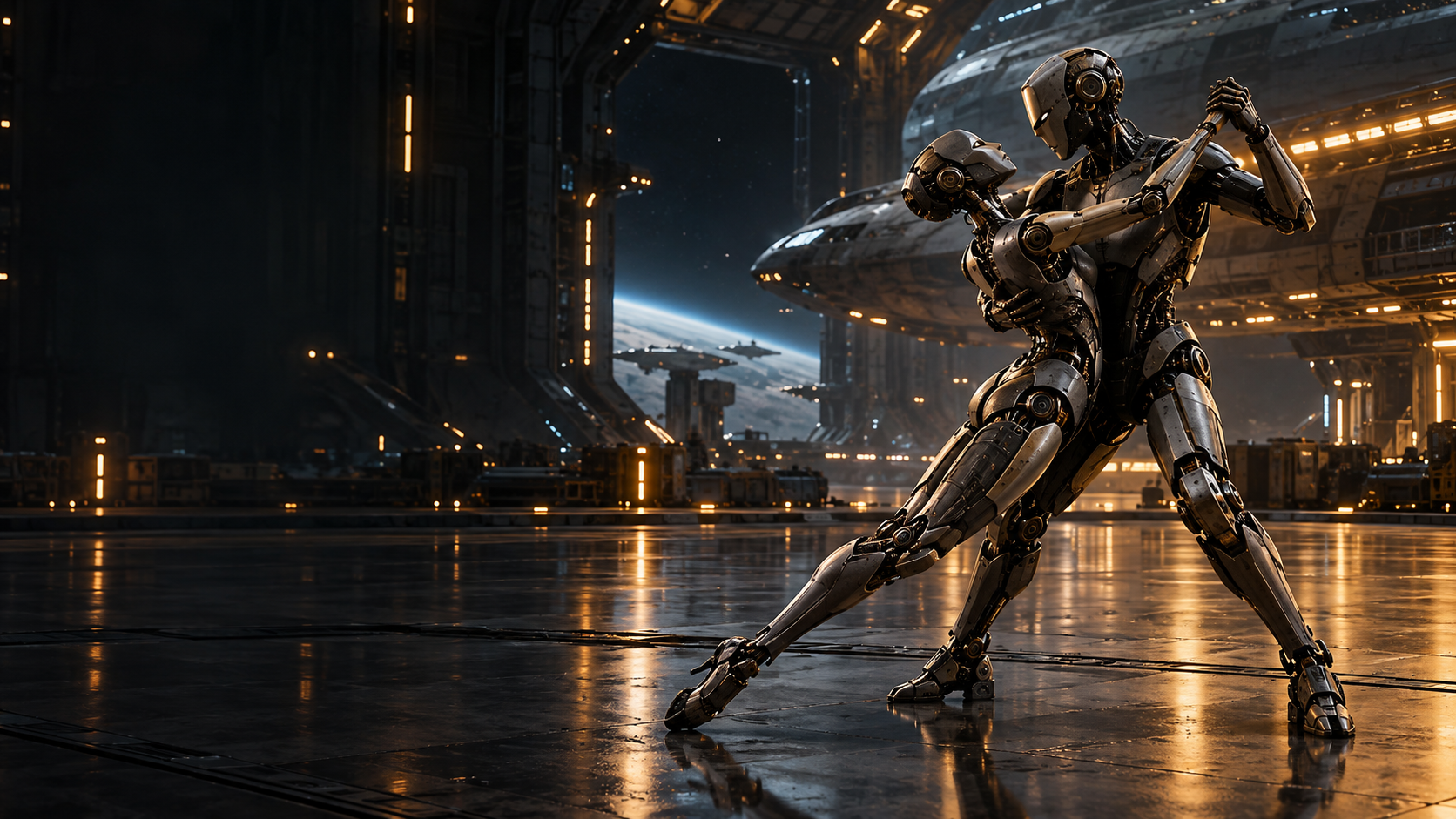
FROM ONE CONTACT TO COORDINATED MOTION
A larger research horizon: many contacts, moving partners, changing support, and shared intention.
A RESEARCH DIRECTION BY TODD MUSCAT
APT provides the geometric starting point. Edinburgh’s RAPT extended relational descriptions into robot assembly. ReKep offers a modern comparison through visually grounded manipulation constraints. [5] [11]
Work coauthored by LeCun explores shaping JEPA representations for goal-reaching value. BodySyntonic asks how explicit physical intentions could make goals and predicted outcomes more useful for motion development. [12]
The hypothesis is practical: a shared representation of body–world relationships could connect what we ask, what a model predicts, and what a robot actually does.